Digital logic nand gate(universal gate),its symbols & schematics Transistor logic gates Transistor gate
Bipolar Junction Transistor, Nand Gate, Logic, Gates, Circuit, Word
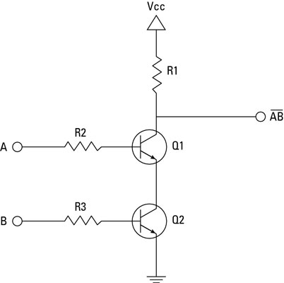
Use transistors to build a nand gate
Gate transistor npn nand circuit diagram schematic breadboard sully technologies station pn2222a led
Electrical – current and voltage in cmos logic gate – valuable tech notesCircuit diagram of cmos nand gate Gate nand transistors using wikipedia cmos logic gates diagram schematic electrical wiki fileCircuit nand gate input transistor two diagram seekic ends basic ic.
Gate nand circuit diode using logic gates dtl transistor gif junction anyNand gate transistor diode logic using operation circuit explain its universal works electronicspost A standard digital cmos nand3 gate and its internal transistorNand gate circuit diagram using transistor.

Npn transistor nand gate circuit
Nand gate schematic diagramBipolar junction transistor, nand gate, logic, gates, circuit, word Using transistors as logic gatesExplain the logic nand gate with its operation and how it works as a.
Nand gate using diode circuitNand gate circuit diagram and working explanation Nand gate diagramNand gate implementation transistors circuit diagram electrical.

Nand gate transistor diagram diagram media
Nand gate transistor circuitWhy does the ttl nand gate use a 4 transistor design instead of 2 Electronic – how does the nand gate work using transistors – valuable2 input nand gate circuit diagram.
The transistor nand gate circuit with two input endsCircuit diagram nand gate .